Removal
Remove the trumpet housing(s).

Disconnect the brake supply pipe (1) located above the centre housing that comes from the brake master cylinder. For tractors fitted with GTA1540 transmission (50 kph), the brake supply pipe (1) comes from the block/valves (1) fitted to the cab's front bulkhead.

Using a manual hydraulic pump connected to the union (3), drive out the piston (2) from the centre housing.

Remove the "O" rings (3) (4) fitted respectively on the centre housing and the differential support. "O" rings J, located between the differential supports and the centre housing, seal the brake piston chambers.

If seal(s) is/are to be replaced, remove the differential support(s).
Refitting
Clean and check all components. Replace those that are defective. In particular, check the wear on the brake plate, the sealed compartment or the spacer (depending on type of trumpet housing).
If removed, refit the differential support(s) fitted with a new "O" ring J.
Before the final refitting of the piston (2), test fit the piston in the centre housing, temporarily excluding the "O" rings (3) (4). This temporary fitting allows you to check that the piston can move freely in its bore and on its stop pins. During fitting, any friction points must be eliminated and problem parts must be identified. Remove all impurities from the piston chamber. Definitively refit the piston, but only after a satisfactory test fitting has been carried out.

Lubricate the new "O" rings (3) (4) with clean transmission oil. Fit them into their respective grooves (centre housing and differential support).
If possible, turn the brake piston so that the majority of the lubricating ports around its rim are facing upwards (depending on piston type).

Fit the piston into the centre housing by aligning its pin housings with the stop pins (6). Fit the piston (2) using a makeshift tool and two screws V of suitable length. These two screws are tightened gradually and alternately during the fitting process. For tractors fitted with GTA1540 transmission (50 kph), carefully monitor the fitting of the piston inside its return travel limit mechanism (3).

If necessary, fit by gently tapping with a plastic hammer in diametrically opposed positions around the piston rim. The return travel limit mechanism (3) means you have to push the brake pistons right back to the bottom of their cavity (pushing the brake pistons is made easier by gently unscrewing the centre housing and the bleed valves or pipes coming from the block/valve assembly). In this way, the mechanism (3) can once again return the brake pistons correctly if one or more of the following components has been replaced:
- brake discs;
- brake plates, compartment (single or sealed) or spacer (depending on the type of trumpet housing);
- brake pistons and/or "O" rings (3) (4).
Remove the tool. Check that there are no seal fragments on the piston circumference.
Brake piston leak test
The brake piston leak test can only be carried out correctly if the pressure gauge and compressed air supply line are completely sealed. Figure shows a simplified pressure gauge design. Other more complex pressure gauges can also be used.

Fit the tool used to retain the piston (2) against the centre housing.
Connect the pressure gauge to the union (3).
Supply the brake piston with compressed air at approximately 3 bar to position the seals (3) (4) in their respective groove.
Close the valve. Disconnect the compressed air source. Open the valve.
Supply the system again at approximately 0.3-0.4 bar to test the tightness of the seals (3) (4). Close the valve. Check that the pressure gauge needle remains still for approximately one minute. Shut the compressed air inlet when the test proves satisfactory. Remove:
- the pressure gauge;
- the piston retaining tool.
Reconnect the brake supply pipe. Refit the trumpet housing(s).
Thoroughly bleed the brake system.
Road test the main brakes. Check tightness of:
- the trumpet housing seals;
- the unions and the pipes (brake supply and lubrication pipes).
Disassembling, reassembling and adjusting the return travel limit
mechanism of the brake piston on 50 kph tractors
On tractors fitted with GTA1540 transmission (50 kph), each brake piston (2) is assisted by a return travel limit mechanism. This mechanism, which comprises three assemblies (3), allows:
- the piston to release itself from the brake disc by approx. 0.7 mm when the brakes are inactive;
- the "drag" effect to be minimised.

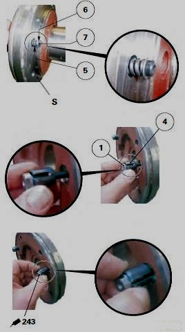
The three assemblies (3) occupy an equidistant position on each differential support S. An assembly comprises:
- an M6 x 40 screw (7);
- a flat washer (6);
- a spring (5);
- a Mecanindus pin (4);
- a shouldered nut with flat sections (1);
- a locking screw (8).
Disassembly
The differential support(s) must be removed in order to disassemble the brake piston's return travel limit mechanism.

Remove:
- the brake piston(s) (2);
- differential support(s) S.
Place the differential support(s) on a workbench.

On faces F and F1 of differential support(s) S, remove an assembly (3) including:
- the locking screw (8);
- the shouldered nut with flat sections (1) (support the M6 screw (7));
- the Mecanindus pin (4);
- the M6 screw (7);
- the flat washer (6);
- the spring (5).
Repeat step for the other two assemblies (3).
Reassembly
Clean and check all components. Replace those that are defective.
On faces F and F1 of differential support(s) S, refit:
- the M6 screw (7);
- the flat washer (6);
- the spring (5);
- the Mecanindus pin (4);
- the shouldered nut with flat sections (1), with its thread lightly smeared with Loctite 243 or equivalent.
Settings
Adjust each assembly (3) of the brake piston's return travel limit mechanism, proceeding as follows for each assembly:
- Tighten the shouldered nut (1) with flat sections (M6, 100 pitch) to a torque of approximately 1 Nm (spring coils almost joined).

- Slacken off this nut between approximately half and three quarters of a turn: this corresponds to an anti-clockwise rotation of 216� to 234� or 60% to 65% of a turn. By adjusting each assembly (3) of the return travel limit mechanism in this way, a gap E of approx. 0.60 to 0.65 mm is achieved between the piston (2) and the brake disc (35) when the main brake is inactive.

0 comments:
Post a Comment